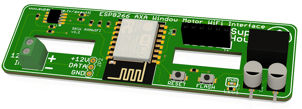
Add WiFi control to the AXA Remote 2.0 electric window motor.
The AXA Remote 2.0 uses either an infra-red remote control for manual control, or a LIN Bus interface for integration with compatible home automation systems. It can be powered batteries, or via an external power source.
This module sits inside the battery compartment and connects to the LIN Bus interface of the controller, giving it a WiFi interface for integration with home automation systems via MQTT.
WiFi devices aren’t practical to run long-term on batteries, so the module is designed to mount inside the battery compartment of the AXA Remote 2.0 where the batteries would normally go. Power is supplied using the external power connecter.
Note: This project is not yet available, because I’ve been experimenting with a couple of different versions and then got distracted by other things! I’ve designed versions for both ESP-01 and ESP-12 modules, and with various power supply options. I’m also skeptical about the safety of using WiFi to control physical access to a house: if someone manages to take remote control of a window motor, they can get into the building.
I’ll get back to this project if people are interested in it.
It’s surprisingly easy to make your own simple air quality sensor. All you need is a cheap laser-scattering particulate matter sensor, a Wemos D1 Mini, a soldering iron, and Tasmota.
Part 1 showed how to make the simplest possible air quality sensor. Make sure you’ve seen that first, because Part 2 continues from Part 1 to add a 128×32 pixel OLED display and a mode button. We’re also going to install custom firmware to make the sensor last longer.
Printing a case is totally optional, of course. You can use whatever enclosure you like. My case has been designed to be a press-fit over the PMS5003, which holds the two halves together by friction. See the link above to download the STLs if you want to print it yourself, or you can buy a case from me if you don’t have access to a printer. I’ll include a 6x6x9mm tact switch with the “Display” version of the case:
Put switch into case
The space for the tact switch is very tight.
To fit it into the slot, trim off the pins from the right side and trim the pins on the left side so they are a couple of millimeters long. Bend those leads out at a 45 degree angle, and solder a pair of jumper wires to them.
Push the switch into the cavity in the case as shown above, and guide the wires around the slot to the left and then down.
The button connects between GND and I/O pin D3:
Connect 128×32 OLED to D1 Mini
The 0.91″ 128×32 OLED module already has I2C pull-ups included, so there’s no need to add them. All we need to do is connect power and I2C:
The connections are:
OLED GND to D1 Mini GND
OLED VCC to D1 Mini 3.3V
OLED SCK to D1 Mini pin D1
OLED SDA to D1 Mini pin D2
Connect PMS5003 to D1 Mini
In the “Basic” version of this project, we only needed to connect to the 5V, GND, and Tx pins of the PMS5003. Now we also need to connect I/O pin D6 to the sensor’s Rx pin, to allow commands to be sent to the sensor:
The connections are:
PMS5003 pin 1 (5V) to D1 Mini 5V
PMS5003 pin 2 (GND) to D1 Mini GND
PMS5003 pin 4 (Rx) to D1 Mini pin D6
PMS5003 pin 5 (Tx) to D1 Mini pin D4
Close the case
This can be more tricky than it sounds! Be gentle so you don’t damage anything.
With the electronics sitting neatly in the “back” (or “right”) half of the case, make sure all the wiring is neatly tucked into the slots. It should look something like this:
Slide the other half of the case over the modules, checking that no wires are pinched between the halves. The case should close completely.
Set up Arduino IDE for ESP8266
If you don’t already have it, download and install the Arduino IDE:
By default, the Arduino IDE does not support the ESP8266 processor on the D1 Mini. To add this support, go to the following URL and follow the instructions. The easiest method is to use the Boards Manager:
The “PMS” library is directly embedded within the program, so you don’t need to install it. This is done to force a specific version of the library, which was forked from the official version by GitHub user SwapBap to add extra features. There’s nothing you need to do because it’s part of the project.
In the Arduino IDE, go into “Sketch -> Include Library -> Manage Libraries…“
Then search for each of these libraries, and click “Install”:
The easiest way is to click the green “Clone or download” button near the top right of the page and select “Download ZIP”. Once you’ve downloaded it, extract the folder and put it in your sketchbook directory. You can find the correct location for this by looking in the Arduino IDE preferences.
Configure and compile sketch
Open the Arduino IDE, open the sketch, and have a look at the 4 tabs across the top. You can ignore the first three. Open the “config.h” tab, and modify the settings for WiFi and your MQTT broker:
Plug in the Air Quality Sensor using a USB cable.
Select “Tools -> Board:” and set it to “LOLIN(WEMOS) D1 R2 & mini”. Select the port, and upload the sketch:
After the sketch has uploaded the Air Quality Sensor will reboot, connect to your WiFi and MQTT broker, and show values on the display once it has successfully received data from the PMS5003.
Stay tuned for part 3, which will explain how the sketch works and how to read the data from it.
It’s surprisingly easy to make your own simple air quality sensor. All you need is a cheap laser-scattering particulate matter sensor, a Wemos D1 Mini, a soldering iron, and Tasmota.
Part 1 shows how to make the simplest possible version of the SuperHouse Air Quality Sensor, the “Basic” version.
Part 2 shows how to improve it to make a more advanced “Display” version, Part 3 is a detailed walkthrough of how the firmware works, Part 4 will explain how various Air Quality Index calculations are done around the world, and Part 5 will step it right up with the “Pro” version with VOC sensor.
Here in Australia we’ve recently had a terrible bushfire season, and there’s been a lot of concern about the effects of smoke on air quality. Smoke particles, pollen, and many other forms of air pollution are tiny. Really tiny. Many people have been wearing “PM2.5” face masks, which means they are designed to filter out particles as small as 2.5 microns in size, but pollen and smoke can be even smaller than that.
Detecting tiny particles down in the 0.1 to 10 micron range is hard. Normally you’d need an electron microscope to detect something this small. In fact these particles are so small that they are often smaller than the wavelength of light, which is in the region of 0.5 microns. This means light doesn’t interact with them in the usual way: instead of bouncing off them like a particle, it can bend around them like a wave, and it can also refract inside them like tiny lenses.
Laser-scattering particle detectors pass a laser through a test chamber, with a deflection sensor on the other side. Particles in the test chamber cause the beam to be scattered in different ways, and the deflection sensor can use this scattering to determine the number and size of particles in the chamber.
This process creates a series of concentric rings on the deflection sensor, which can use the spacing of the rings to determine the characteristics of the particles.
The particles that are detected are then categorised, or “binned”, into different size ranges for reporting.
All of this functionality is wrapped up in the tiny Plantower PMS5003 sensor, which provides a serial interface to report the statistics for the particles that it detects.
Reporting is normally provided in a couple of forms.
The simplest number is the PPD value, which stands for “particles per deciliter”. The higher the number, the more particles there are in the air sample.
The most commonly used number is the “ug/m^3” value, which is micrograms per cubic meter. This is the total mass of particles in that size range in a cubic meter of air, so smaller particles will require a higher raw count to add up to the same mass as larger particles.
Parts required
The “Basic” version of the SuperHouse Air Quality Sensor only requires a a Plantower PMS5003, the connection cable that comes with it, and a Wemos D1 Mini. See the links above for sources to buy them.
You can also print your own 3D-printed enclosure, or buy one from me if you don’t have easy access to a printer.
Connect PMS5003 to D1 Mini
The PMS5003 requires a 5V supply because it has an internal fan to keep air flowing through the test chamber, but all its I/O connections are 3.3V.
This is perfect for a D1 Mini, because we can connect the power pins to 5V on the D1 Mini and connect the sensor “TX” pin to an I/O header on the Mini.
Cut the supplied cable off at about 2/3rds of its length. Plug it into the PMS5003 to check the orientation, and then strip and tin the ends of the wires connected to pins 1, 2, and 5.
Connect VCC and GND from the PMS5003 to the 5V and GND headers on the D1 Mini.
Connect TX from the PMS5003 to the D4 header on the D1 Mini, which is GPIO2 for the ESP8266 MCU.
3D printed case
I’ve designed a case that slips over the PMS5003 and provides a space for the D1 Mini and wires. You can download the STLs and print it yourself, or if you don’t have access to a 3D printer you can buy it from me in a variety of colour options.
The case comes in two halves. Insert the PMS5003 into the case first, and then slip the D1 Mini into the space at the bottom. The case is oriented so that if the USB socket is on the side towards the PMS5003 it will be accessible through a slot.
Push the wires down into the case so everything is neat, and then slide the other half of the case over the top. It may take some jiggling to get the wires out of the way and the D1 Mini properly inserted into the slot.
Install Tasmota
There are many ways to install Tasmota on the D1 Mini, but my new favorite is to use Tasmotizer. I did a whole video about how to install and use Tasmotizer, so follow the instructions here if you need to install it:
Once you have Tasmotizer running, connect the D1 Mini using a USB cable and select the port.
Note: As of Tasmota v8.2, support for the PMS5003 has been removed from the normal “tasmota.bin” release binary. Instead, you must select “tasmota-sensors.bin”.
Click the button next to “Release“.
From the drop-down, select “tasmota-sensors.bin” (not the regular “tasmota.bin” as shown above)
Click “Tasmotize!” and wait about a minute for the D1 Mini to be flashed and reboot.
Configure WiFi and apply the “SuperHouse AQS” template
After the D1 Mini has been flashed, click “Send config” in Tasmotizer to open the configuration screen.
Click the checkbox to enable the WiFi section, and put in the details for your WiFi network.
If you use MQTT, click the checkbox to enable the WiFi section and put in the address for your broker. My personal preference is to change the “Topic” entry to “tasmota-%06X” so that the MQTT topics will be dynamically generated using the unique ID of each D1 Mini.
Click the button next to “Template”.
Copy the template below, and paste it into the text box at the bottom of the config screen:
Click “Save” to send the new configuration to the D1 Mini.
It will then restart, and will connect to your WiFi network using the values you just provided.
Connect to Tasmota web interface
You can use a serial console connected at 115200bps to get the IP address directly from the D1 Mini, or look in the management interface for your DHCP server to find the recently added device.
Once you’ve found the IP address, put it into a web browser to load up Tasmota’s web interface.
The module will report its latest readings, updating as fast as the sensor is sending them.
You can also configure the D1 Mini manually if you didn’t use the template above. Starting from a default Tasmota installation, log into the web interface and set up the module as shown below.
Access data via MQTT
Tasmota periodically publishes all the PMS5003 readings aggregated into a single JSON string, in the “../SENSOR” topic.
The topic will depend on the settings you applied for MQTT. In my case, with the “Topic” modified as explained above, the readings are published to a topic that looks similar to “tele/tasmota-5F596F/SENSOR” with the unique ID of this particular device substituted.
The published value will look something like this:
You can parse the JSON using your favorite method, such as with Node-RED. I’ll go over this in more detail in Part 2 when we look at more advanced software options.
The “PMx” values are micrograms per cubic meter. The “PBx” values are particles per deciliter.
Further improvements
This “Basic” version of the SuperHouse Air Quality Sensor is very simple to make, but it has a couple of limitations.
The laser and the deflection sensor in the PMS5003 can degrade over time. After about 6000 hours of continuous use it may begin to decrease in sensitivity. The life of the sensor can be dramatically extended by shutting it down for a couple of minutes, then waking it up, giving it time to stabilise, taking a reading, and shutting it down again. With this change the sensor can last for many years.
There is also no way to interact with the device directly. You have to access it over the network, either by loading the Tasmota web interface or by using the data published to MQTT. Adding a screen and a mode button can make it easy to read particulate levels directly on the device.
Both of these limitations are fixed in the “Display” version of the SuperHouse Air Quality Sensor in the next episode. Stay tuned!
Installing Tasmota onto a device such as a Sonoff is usually done using esptool.py, which is a powerful command line utility but it can be a bit confusing if you’re not used to it. Now it’s been paired with an amazing graphical interface called Tasmotizer that gives you point-and-click convenience, and adds some handy features for configuring your devices:
The Tasmotizer page has good installation instructions, with three options given.
If you use Windows, download the executible and run it.
On Linux or MacOS, you can install using Pip.
If you want the absolute latest development version you can clone the Git repo and install manually.
Use whichever method suits you best. I used Pip to install it on my iMac, my Macbook Pro, and my Ubuntu desktop, and the process went smoothly on all of them. Make sure you have the latest version of Pip, and then use it to install Tasmotizer:
If your Python installation is set up so that new programs are automatically available, it should be possible to simply type in the name and press “Enter”:
tasmotizer.py
However, you may not be so lucky. You may have to find where Pip installed it. Pip can tell you where the files are for a specific package, but its output has horrible formatting that’s hard to interpret. Run this command to see a list of all the files in the Tasmotizer package:
pip3 show -f tasmotizer
The output will include a line called “Location” which shows the directory where the program is located. On my iMac, Pip installed Tasmotizer at:
It’s a pity that Python’s installation management is such a mess, and produces unpredictable results. Hopefully you can find the location for your installation without too many problems.
Once you’ve discovered its location, paste in the appropriate command and press “Enter” to launch Tasmotizer.
Connect the device to your computer
Your target device needs to be connected to your computer using USB, either by directly plugging in a cable or by using a USB-to-Serial adapter. Some devices such as Wemos D1 Mini boards have built-in USB. Sonoff boards don’t have USB so you’ll need to make up an adapter to suit the programming header for your specific board. I’ve done many videos and guides for reflashing various Sonoff models, and the Tasmota site has excellent documentation so follow the appropriate guide to make the connections.
Most Sonoff models use a simple 4-pin header, so I designed the Sonoff Programming Adapter to make it easy to plug in a 3.3V USB-to-Serial adapter with a standard 6-pin header.
Place device into bootloader mode
The ESP8266 / ESP8285 processor needs to be placed into a special bootloader mode before it can have Tasmota installed. This is done by powering it up while the GPIO0 pin is held at 0V, which is usually done using the control button. The sequence is:
Press and hold the button.
Connect power.
Wait a couple of seconds, then release the button.
The device then stays in bootloader mode, waiting for new software to be loaded.
Select device in Tasmotizer
Click the “Refresh” button so Tasmotizer will scan for connected devices and update its list. Use the drop-down to find your target device.
Select the firmware image
Tasmotizer gives you three options for selecting a firmware image.
If you have your own binary, such as a version of Tasmota or some other firmware that you’ve compiled or downloaded, click the “BIN file” radio button and select the file from your local disk.
If you want to install the current release version of Tasmota, click the “Release” radio button and then use the drop-down menu to select the specific flavour of Tasmota for your device.
If you like to live on the edge, you can click the “Development” radio button and use the latest development code that hasn’t been released yet.
Set flashing options
If you want Tasmotizer to make a backup of the existing software on your device, click the “Backup original firmware” option. This will allow you to put it back onto the device later if you change your mind.
If you want to make sure the entire memory of the device is cleared, click the “Erase before flashing” option. This makes sure there is nothing remaining from the previous firmware still left on the device, such as saved configuration options. This is a good idea to make sure you have a fresh start and Tasmota won’t read data from a previous installation.
Flash the firmware
With the correct firmware image selected, click the blue “Tasmotize!” button. Tasmotizer will download the selected image (if required) and install it onto your device.
You’ll see a progress bar as the image is installed. Once it’s done, you’ll be prompted to restart it.
Congratulations! Tasmota is installed.
If you want to configure it manually you can do that by following the usual Tasmota instructions. However, Tasmotizer can save you a lot of time by allowing you to do some basic configuration via USB while it’s still connected to your computer.
Select config options
Click the “Send config” button to open a configuration window.
WiFi setup
Click the check-box to enable the WiFi section, and enter your WiFi network name and password.
Module/template setup
Click the check-box to enable module/template setup, which gives you options to either select a pre-defined module or apply a template. Applying a module profile or a template allows your device to be configured entirely from Tasmotizer.
If you have a common device, select “Module” and find the device in the drop-down list.
If you have a device that has a template provided for it, select “Template” and then paste the template into the text box. There are more than 1000 templates provided at the Tasmota Device Templates Repository.
MQTT setup
If you use MQTT in your home automation system, click the check-box to enable MQTT setup and put in the address of your MQTT broker.
You can manually define the topic for this device (such as “bedroom1”) but my personal preference is to allow the device to generate the topic based on its own internal ID. That way all devices come up with their own unique topics, which can then be referenced in the home automation system.
To do that, change the “Topic” setting to add the extension “-%06X”, like this:
tasmota-%06X
What this will do is take the last 6 hexadecimal digits of the device ID and append them, so the topic will be something like “tasmota-6A0B15”. This value is then used to generate the FullTopic value below it automatically, by replacing the “%topic%” placeholder. The result will be full topics that look similar to:
I like this approach because it means that all my Tasmota devices can have the same configuration, but they still end up with unique MQTT topics.
Send config to device
With all your preferred options set, click the “Save” button. Tasmotizer will send your configuration to the device, and you’re all done. This step is a bit strange, because it happens so fast that it seems like it couldn’t possibly have done anything, but if you get a confirmation dialog then you’re all set.
Finished! Your Tasmota device will now reboot and apply the settings that you configured, so after a few seconds it will be on your network. Just follow the Tasmota documentation to learn how to link it to your home automation system.
This device is not yet available. We’re still testing prototypes! If you’d like to be involved in the discussion about the design or to help with testing, please join the SuperHouse Discord server.
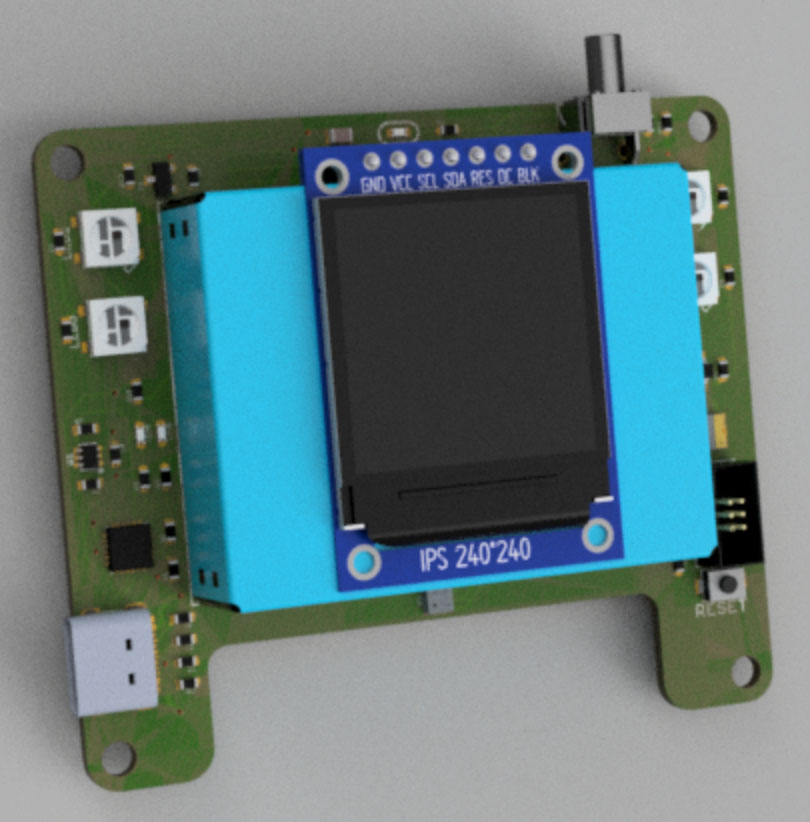
Measure the level of harmful pollution in the air, including particulate matter (smoke, dust, etc) and gases.
The Air Quality Sensor combines an ESP32 with a Plantower PMS7003 particulate matter sensor and a Bosch BME680 environmental sensor to report:
PM2.5 (2.5 micrometer) particle count
PM2.5 (2.5 micrometer) particle count
PM10.0 (10 micrometer) particle count
Temperature
Humidity
Atmospheric pressure
Volatile Organic Compound (VOC) gas levels, including carbon monoxide, ethanol, and alchohol
Reports values via USB, on the 240×240 colour LCD, or via WiFi to an MQTT broker. Also has RGB LEDs, so it can display the current level of air pollution by glowing different colours.
This hand heater is not yet available. We’re still testing prototypes! If you’d like to be involved in the discussion about the design of the heater, please join the SuperHouse Discord server and check out the #assistive-technology channel.
Controlling an electric wheelchair can be difficult in winter, when cold hands and fingers can stop you from accurately moving the joystick. This small hand heater can be mounted on a wheelchair so that it blows warm air over the joystick area to keep your hand warm and mobile.
The example firmware provides multiple power levels, MQTT control and reporting over WiFi, over-temperature shutdown, Bluetooth control, and fan speed sensing to detect a stalled fan.
Features
24Vdc power to suit most wheelchair batteries
Espressif ESP32 processor (Arduino compatible)
Speed-controlled fan with tacho sensor
30W resistor heating array
Output temperature sensor
CAN bus interface to receive commands and report status
3.5mm socket for external control button, compatible with assistive buttons
Power from either a 2.1mm DC jack or via the CAN bus connector
Mount using camera fittings such as common Go-Pro brackets
WiFi to integrate with home automation systems using MQTT
Traditional house wiring has an active and a neutral that meander around the ceiling to each light location, with the neutral connected directly to the light. The active comes down through the wall to the light switch, and then the output from the switch goes back up the wall to the active side of the light fitting.
This works well with passive switches, but most smart light switches need a neutral connection to power their own electronics. With only the active wiring going to the light switch, it can be very difficult to replace existing switches with smart switches.
Building codes in many countries now require that all light switches must have a neutral connection, but this is a recent change so most existing houses don’t have a neutral wire at the switches.
Smart light switches that are designed to be installed in place of existing switches and don’t require a neutral connection are generally called “no-neutral” switches.
Sonoff T4EU1C
The Sonoff T4EU1C is a no-neutral smart light switch with WiFi, so it only needs the active-in and active-out connections that are already found at most light switch locations. It operates by drawing a small amount of power through the light even when the light is turned off, so that it can run its own electronics.
The T4EU1C consists of two PCBs joined together by an 8-way header. The top PCB is the low-voltage logic board, which includes the processor, WiFi antenna, 3.3V voltage regulator, touch sensor pad and driver IC, and the programming header:
The bottom PCB is the high-voltage mains board, which includes a 12V-output mains power supply, and a relay and Triac for controlling the active output to the load:
Re-flashing the firmware with Tasmota
WARNING: There are problems running Tasmota on this particular model. It worked for me, but many other people have problems with the touch switch even when Tasmota is installed correctly. The rest of the Sonoff operates properly and it can be controlled by WiFi, but the touch sensor doesn’t work. There are a few people collaborating right now to figure out why this happens. If you’re feeling lucky, you can give it a try. However, it’s possible that you won’t be able to use the touch sensor until this problem is solved. There is ongoing discussion about it on the SuperHouse Discord server so please join in.
Just like all other Sonoff models so far, the firmware on the T4EU1C can be replaced with alternative open-source firmware to add new features such as local-network operation, MQTT, etc.
However, out of all the Sonoff models that have been released this is perhaps the most difficult one to re-flash. It can be done if you have the equipment and ability to make soldered connections to very tiny parts on the PCB, and this particular board also seems to have some strange requirements to force it into bootloader mode.
The common process for putting a Sonoff into bootloader mode is to hold the GPIO0 pin low (ie: to GND) while powering-up the board. In my testing, I found that this would result in the Sonoff appearing to accept the upload of the new firmware, but a strange checksum error would occur in the flash memory and it wouldn’t boot properly afterwards.
The process that I’ve found to work requires making a connection to the RESET pin as well as GPIO0, so that it can be put into bootloader mode after it has already been powered-up and connected to the programming adapter.
Programming connections
Re-flashing the firmware on the T4EU1C requires the usual connections to the programming header found on the logic board as shown in the picture above, plus connections to GPIO0 and RESET to force it into bootloader mode. Connection to the programming header is easy, because it’s exposed on the logic board in the same format as almost all other Sonoff models.
The difficulty is gaining access to GPIO0 and RESET, because neither of these lines are brought out onto pads for easy connections.
The most convenient place to make a connection to GPIO0 is the very thin track that runs diagonally on the top side of the logic board. Use a scalpel to carefully scrape away some of the green solder mask along the track. Be very careful that you don’t cut the track, and don’t scrape away the solder mask from the surrounding copper areas. If you do, it will be much harder to connect a wire to the track without causing a short circuit to the surrounding copper.
RESET is even harder. The only place it is exposed is on the end of a tiny resistor labelled “R3”, with a very small gap to an adjacent resistor. The connection must be made very carefully and quickly. If the resistor is allowed to heat up for more than about one second, the solder on the other end will also melt, and the resistor will move.
To control the GPIO0 and RESET pins, I soldered a pair of momentary buttons together and connected 3 lengths of very thin wire-wrap wire to them:
The common (blue) wire is soldered to GND on the logic board.
One switched wire (yellow, in my example) is soldered to the GPIO0 track after scraping off the soldermask.
One switched wire (red, in my example) is soldered to the RESET line by attaching it to the bottom end of the resistor marked R3.
Be extremely careful when making these connections to the PCB. It’s very easy to damage the tracks or the parts, and if you don’t have the necessary equipment and skill to rework the board you may destroy your Sonoff.
Programming header connections
Use a USB-to-Serial adapter and jumper wires to connect the Sonoff to your computer. Make sure the USB-to-Serial adapter supports 3.3V mode, because the ESP8285 can be damaged if you connect 5V to it. The connections are the same as explained in previous videos:
In this case the power switch doesn’t matter, because we will use GPIO0 and the RESET line to force the Sonoff into bootloader mode.
The connections can be made with loose jumper wire, or you can use my Sonoff Programming Adapter which does the same thing.
Tasmota upload
The T4EU1C has the same pin assignments as a Sonoff Basic, so download the generic pre-compiled Tasmota binary.
Install the “Esptool” program, and open a terminal in the same directory as the Tasmota binary.
With the Sonoff connected to your computer as described above, and the buttons ready to assert GPIO0 and RESET, run Esptool as below:
You may need to adjust the serial port address to match your computer.
Immediately after you press “enter”, follow this sequence:
Press and hold both buttons that you have attached to the Sonoff.
Wait about 2 seconds.
Release the RESET button.
Wait about 2 seconds.
Release the GPIO0 button.
You should see Esptool immediately identify the processor on the Sonoff and begin uploading Tasmota. This entire process will take about 30 seconds. You should see output similar to this:
 esptool.py v2.6
 Serial port /dev/tty.SLAB_USBtoUART
 Connecting…….._
 Detecting chip type… ESP8266
 Chip is ESP8285
 Features: WiFi, Embedded Flash
 MAC: 2c:f4:32:a8:18:8b
 Uploading stub…
 Running stub…
 Stub running…
 Configuring flash size…
 Auto-detected Flash size: 1MB
 Compressed 515872 bytes to 355877…
 Wrote 515872 bytes (355877 compressed) at 0x00000000 in 31.3 seconds (effective 131.7 kbit/s)…
 Hash of data verified.
 Leaving…
 Hard resetting via RTS pin…
At the end of the upload, Esptool will report 100% completion and say that it is resetting the board. However, it can’t actually reset the board because it doesn’t have any connection to the RESET line. You can press the reset button yourself, or disconnect the Sonoff from the programmer and re-connect it to cycle the power.
The Sonoff will then begin the normal Tasmota setup process, creating a WiFi network and opening a serial connection through the programming header. Follow the usual steps as shown in the Tasmota documentation to set it up, selecting “Sonoff Basic” as the module type.
The T4EU1C should then behave as expected, with control using the touch sensor on the front panel and also via WiFi.
ESP8266 / ESP8285 boot messages
If the ESP8285 didn’t enter bootloader mode properly, the Tasmota upload may have appeared to work in the previous step but the Sonoff still won’t boot. Esptool can show its normal upload progress, ending with the message saying it is 100% complete and resetting the board. But then when you power cycle or reset the board, it never comes online and you can’t tell why.
While booting, the ESP8285 outputs debug information to the programming header at the unusual baud rate of 74880bps. Most serial terminal programs can’t operate at that speed, because it’s not a standard baud rate.
The “CoolTerm” serial console is available for Mac, Linux, and Windows, and can be configured to support 74880bps.
Download and install CoolTerm following the instructions on its site.
After it has been installed, find where the binary is located on your computer. On a Mac, it’s typically inside the “/Applications” directory.
In that same directory, make a text file called “baudrates.ini” and put in the number “74880” without quotes or any other characters. Save the file, then start up CoolTerm.
You should now find 74880bps listed as a supported baud rate in the “Options” menu.
Select 74880 as the baud rate, select the serial port for your programming adapter, and click “OK”:
Click the “Connect” button to open the connection to your Sonoff, and then press the reset button on the Sonoff to force it to reboot.
If the ESP8285 has failed to boot, it will display an error similar to this:
If you see this message, there is an error with the program stored in flash memory and you should try following the steps above to flash the Sonoff again.
I’ve resisted for ages, so viewer Lorenzo took matters into his own hands and set up a Discord server for SuperHouse 🙂
Within 24 hours of being announced, there are now more than 200 people on the server! To join the discussion about SuperHouse projects, home automation, MQTT, Home Assistant, OpenHAB, Tasmota, and many other things, go to this link for an invitation:
Make the Sonoff smart power controller even more awesome by installing the Tasmota open source firmware.
Tasmota adds many new features, and allows you to integrate Sonoffs into an existing home automation system without relying on external cloud services. It includes MQTT support, Belkin WeMo emulation, easy configuration using a web browser, and you don’t even need a compiler or IDE to install it.
Note: Since this video was released, the Tasmota project has changed its build process so that the binaries are now called “tasmota” instead of “sonoff”. I have edited the text instructions below to match, but screenshots and the video still refer to the old name.
To load new firmware onto a Sonoff, you need four pieces of hardware:
A compatible Sonoff model or equivalent (more than 50 devices are supported by Tasmota)
A USB-to-Serial converter that can run in 3.3V mode (don’t use a 5V converter!)
Jumper wires or a programming adapter to connect the USB-to-Serial converter to the Sonoff
A computer with WiFi. You can use a mobile phone for the WiFi steps if you prefer.
You can make the connections using jumper wires and the instructions in my previous video, or you can use my handy little programming adapter. Both methods do exactly the same thing: my programming adapter just makes it neat and easy.
Make sure the Sonoff is totally disconnected from any mains power.
Don’t proceed unless you have done that! Connecting your computer to a Sonoff while it is connected to mains is extremely dangerous.
Details of the electrical connection are shown in the previous episode, so check that out if you need more information.
Step 2: Download Tasmota
The Tasmota firmware and its documentation is available at github.com/arendst/Sonoff-Tasmota, including both firmware and pre-compiled binary releases. If you want to compile the code yourself that’s fine, but you don’t need to if you just want the latest version. The binary releases are at:
There is a big list of binaries for each release, which can be confusing if you don’t know which one you need. The binaries fall into several categories which are outlined on the releases page.
For most devices, you should choose the binary called “tasmota.bin” which includes all the features required for the majority of compatible hardware.
The binaries with 2-letter country codes appended, such as “tasmota-IT.bin”, have the exact same functionality as the standard “tasmota.bin” but with different languages for the user interface. If you want to run Tasmota in a language other than English, select the appropriate “tasmota-XX.bin” file.
Whichever version you select, download it to your computer.
I prefer to rename the binary file so that it includes the release version, such as “tasmota-8_4_0.bin”. That way if I come back to it later, I can see what version I downloaded.
Step 3: Download and install esptool
Esptool is a utility that can be used to read and write the flash memory on devices using the ESP8266 and ESP8285 microcontrollers, including all current Sonoff models. It’s written in Python so you will need a working Python environment on your computer.
Follow the instructions on that page to install it on your computer.
Step 4: Find serial device
Your USB-to-Serial converter connects to your computer by USB, and appears to the computer as a virtual serial port. The exact location of the virtual serial port will vary depending on the type of converter that you have, what operating system you use, and which physical USB port you plug the converter into.
If you have the Arduino IDE installed, a good way to find the location of the virtual serial port is to start the IDE, look at the ports list in Tools -> Port, then plug in the converter and check the ports list again to see if a new port has appeared.
On my Mac, the port appeared at /dev/tty.usbmodem14201, so I’ll use that in the following examples.
Step 5: Put Sonoff into bootloader mode
Disconnect power from the Sonoff, hold the GPIO0 pin low, and reconnect power. Then release GPIO0. This process is explained in detail in the previous video.
This will put the Sonoff into a mode where it waits for new firmware to be loaded.
OPTIONAL Step 5b: Back up original firmware
If you want to make a backup of the original firmware so you can restore it back to factory-original later, jump to the addendum near the bottom and then return here. Otherwise, carry on!
Step 6: Upload the Tasmota firmware
Open a terminal, and go into the directory where you have the Tasmota binary. Use esptool to push it to the Sonoff using the serial port location that you found earlier:
The “write_flash” command tells esptool to send new data to the flash memory
The “-fs” parameter is the flash size. Put this parameter in if you know it. If you don’t, you can omit this parameter and esptool will attempt to auto-detect the flash size for you
The “-fm” parameter is the flash mode to use
The “0x0” parameter tells esptool to start writing into flash from address 0
The final argument is the binary image to load
Uploading the binary takes about 30 seconds.
While esptool is doing the upload it will report useful information about the hardware in your Sonoff, including the MAC address. This can be extremely useful if you want to put a DHCP static lease into your router fix your Sonoff to a specific IP address. You can copy and paste the MAC address out of the terminal and save it in a document or spreadsheet for future reference if you want to.
Step 7: Connect to Sonoff via WiFi
Disconnect the Sonoff power power, then reconnect it. When the Tasmota firmware starts up and doesn’t find any existing configuration, it goes into a setup mode and creates its own WiFi network. The network will have a name similar to “Tasmota-6392”, with the 4 digits based on the last part of the unique MAC address of the Sonoff hardware.
On your computer or smartphone, go into WiFi settings and look for a network with a name similar to this. Make a note of the network name, because you will need it in a moment!
Connect to the Sonoff’s WiFi network without any username or password. Your computer should then automatically open a captive portal, with a WiFi configuration screen for the Sonoff.
Enter the WiFi settings for your normal network into the Sonoff. You can enter them directly, or you can click the “Show wifi networks” link to have the Sonoff scan for available networks so that you can select the right one and then enter the password manually.
Enter the details, and click “Save”.
The Sonoff will then reboot and attempt to connect to your normal WiFi network.
This will cause your computer to drop off the temporary WiFi network that was created by the Sonoff, and reconnect to your normal network.
Step 8: Connect to Tasmota configuration interface
Open a web browser, and enter the address of the Sonoff using the network name that you noted in Step 7 with “.local” added to the end. For example, the address could be something like
tasmota-6392.local
This will open a configuration interface where you can view information about the device, change its settings, backup and restore the configuration, install firmware updates, and control the output.
Many of the configuration options are explained in the video. Explore the menus and set up the Sonoff to suit your home automation system.
Addendum: Reconfiguring from scratch
If your home WiFi changes or you take the Sonoff to another location, it will keep trying to connect to the network that you originally configured and you won’t be able to control it.
If this happens, you don’t need to re-flash Tasmota. Instead, you can put it into WiFi recovery mode.
Tasmota can use the button on the Sonoff to put it into special modes. If you quick-press the button 4 times, it will restart the setup process and create its own WiFi network again just like in step 7. Then you can connect to its WiFi, and give it new details so it can connect to your main WiFi network again. Your other settings will be retained so you don’t need to set them again.
If you press and hold the button for more than 40 seconds, Tasmota will clear all its settings, reboot, create a WiFi network, and begin the setup process from scratch.
Addendum: Backing up and restoring original EWeLink firmware
If you want to keep the option of returning the Sonoff to factory-original condition, you can download the original firmware out of its flash memory and save it for later use. Obviously this has to be done BEFORE you flash Tasmota onto it!
Do everything up to Step 5, but DON’T continue with Step 6. Instead, use esptool to determine the flash size of the Sonoff. Using your own serial port address, run a command like this:
esptool.py -p /dev/tty.usbmodem142101 flash_id
This will give a result that looks something like this:
jon@Jonathans-MacBook-Pro:~/Downloads$ esptool.py -p /dev/tty.usbmodem142101 flash_id

esptool.py v2.6-beta1

Serial port /dev/tty.usbmodem142101

Connecting….

Detecting chip type… ESP8266

Chip is ESP8266EX

Features: WiFi

MAC: dc:4f:22:2b:c8:63

Uploading stub…

Running stub…

Stub running…

Manufacturer: e0

Device: 4014

Detected flash size: 1MB

Hard resetting via RTS pin…
You can see the result “Detected flash size: 1MB” near the end.
The Sonoff will have reset back into normal mode, so put it back into bootloader mode in the usual way, then use a command like this to download the existing flash memory and save it in a local file:
Pay attention to the value “0x100000” above. That example will read the flash starting at address 0, and continuing on to the 1MB point. If you have a 2MB flash, you’d use “0x200000”, for example.
On my laptop, it looks like this:
jon@Jonathans-MacBook-Pro:~/Downloads$ esptool.py -p /dev/tty.usbmodem142101 read_flash 0x0 0x100000 sonoff-ewelink.bin
 esptool.py v2.6-beta1
 Serial port /dev/tty.usbmodem142101
 Connecting….
 Detecting chip type… ESP8266
 Chip is ESP8266EX
 Features: WiFi
 MAC: dc:4f:22:2b:c8:63
 Uploading stub…
 Running stub…
 Stub running…
 1048576 (100 %)
 1048576 (100 %)
 Read 1048576 bytes at 0x0 in 94.0 seconds (89.2 kbit/s)…
 Hard resetting via RTS pin…
After it’s finished, you will have the original flash memory saved on your computer in a file called “sonoff-ewelink.bin”.
Then continue with installing Tasmota.
Later, if you change your mind and want to put the original firmware back in place, you can follow the normal steps for installing Tasmota but instead use the file you saved. The command will look similar to this, but with your serial port address substituted: