My home automation light switches have gone through a series of versions, starting with very complicated switches that all had Ethernet built in. Over time I’ve simplified the system so now the light switches themselves are electrically very simple: they’re just illuminated buttons on a breakout board with an RJ45 connector, and absolutely nothing else in them.
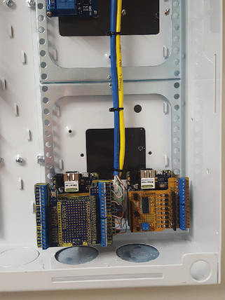
The switches connect to a pair of centralised light switch controllers over Cat-5 cable, so that it can detect when the buttons have been pressed and report events to MQTT.
In this episode I show some of the previous versions of my light switches, and then show how I built an Arduino based light switch controller.
There’s also a general introduction to the I/O breakout schema that I use at I/O Breakout. I’ll probably cover this in detail in a future episode because the same breakout shield will be used in other projects.
The light switches themselves are just illuminated buttons on a breakout board, mounted on a standard wall plate. The 4-button panel uses all 4 available data lines. The 3 and 2 button panels simply use fewer data lines. Click on the schematic for a larger version:
I didn’t spend much time in this episode explaining the current version of my light switches because I’m going to cover it in much more detail in the future. This episode is mostly about the controller.
Addendum: Chris Aitken has written a handy library to detect different button press events, such as single-press, double-press, and press-hold. This could be used to extend the functionality of the button controller significantly. Check it out: github.com/caitken-com/MultiFunctionButton
I’ve been lucky enough to have worked with an electrician to totally rewire my house for home automation, so it works in a very different way to a normal house. This episode traces through how power arrives at my house, is distributed to a pair of sub-switchboards, and from there goes out to loads such as lights. It also covers the important pieces of the system including MQTT and OpenHAB.
General information about MQTT is available at the official MQTT site. The site doesn’t get many updates because the protocol standard itself is fairly stable and well established, but it’s a good reference site with links to many MQTT-related projects. See mqtt.org.
There are many MQTT broker implementations available, written in various programming languages and with different features and levels of performance. I use Mosquitto, which has been around for many years and has never let me down. Note that your MQTT clients won’t care what broker you use or what language it’s written in, provided it supports the features they need. Mosquitto is written in Java, but I typically connect to it from Arduino-based devices. See mosquitto.org.
OpenHAB is currently the main rules engine that I use, which also takes care of state management and provides an app for iOS and Android. I’m still running the v1.x release series, but v2 is out now which is a major rewrite. See openhab.org.
For a general purpose rules engine that communicates using MQTT, check out Node-RED. With a drag-and-drop editor based on Node.js, you can create rules right in your browser. I don’t currently use this, but I’ll probably replace my current home-brew rules engine with Node-RED some time in the future. See nodered.org.
Fantastic guide by forum member @aspork42, with extra resources and a cost calculator if you want to build something like this yourself: Light Switches – How Jon does it
Building a home automation system is a lot of fun, but there’s a serious issue you need to consider: what will happen when you’re gone? Will anyone else be able to figure out the system that you put together?
A couple of years ago, software developer Chris Yeoh passed away after a battle with cancer. Even with time to plan, his passing still left some systems in his house inaccessible to his wife and young daughter. His situation made me think long and hard about what would happen to my family if the same thing happened to me.
I have a couple of suggestions for ways to prepare your system for dealing with a future without you.
Bootstrapping documentation
If you’re gone, and a random electrician is called in to figure out why the lights aren’t working, will they throw up their hands in disgust and walk away? The first thing they’ll do is open the switchboard to orient themselves, so put some obvious bootstrapping documentation right there at the switchboard.
When I first started taking electronics apart in the 1970s, it was normal for major appliances to have physical documentation inside them. If you take the back cover off an old black and white TV, it may have the complete circuit diagram glued inside for the benefit of service technicians. I’ve even opened up old TVs to find a complete factory service manual packed inside.
I keep a master document in Google Docs, and a hard copy on a clipboard hanging next to the main switchboard. Whenever I make a change to the cabling or anything else relevant, I write the changes in the hard copy. When a few changes have accumulated, I take the clipboard to my computer and edit my master copy. Then I print it out again, put it on the clipboard, and leave it with the switchboard.
My document contains:
Name and phone numbers of myself and my wife.
Name and phone number of our electrician.
WiFi SSID and password.
Name of my ISP, account ID, password, tech support phone number, and fault history.
Name of my cable TV provider, account ID, password, and fault history.
A plan of my house, with important locations (such as all switchboard locations) marked.
A definition of the labelling scheme for network connections.
A list of Ethernet ports and their uses.
A definition of the labelling scheme for power cables.
A list of relay outputs controlling loads in the house.
You can see a template version in Google Docs, and either duplicate it for your own use or download it as a Word doc or other format:
When you make something for your home automation system it’s usual to test the firmware, modify it until it’s working just right, and then walk away and forget it. The source code for your project is probably sitting in some obscure location on your computer, which nobody else can access. Or if they can access it, how do they know this particular Arduino is running the sketch called “SensorShield4MQTT” instead of the other one called “SensorInputsMQTT”? Or which versions of the libraries you compiled it with?
When I finish a project, I copy the source code and associated libraries onto a cheap USB memory stick or an SD card, and then put it inside the project box or attach it with a cable tie so that it always physically stays with the project.
Later, if I ever update the firmware, I also update the memory stick so that I know 100% for sure that it always contains the exact source code that is currently running on the device.
This has saved me hours of frustration on multiple occasions, and if anyone else ever wants to fix the systems I’ve built this should put a smile on their face.
Other ideas?
I’d love to know if you have other suggestions! Please comment below.
Finally, please consider supporting a cause such as Free To Breath and help fight cancer.
Electric window motors allow your home automation system to open and close your windows as required. This could be useful for opening windows to allow ventilation, or to make sure all windows are automatically closed and locked when you leave home.
I recently got my hands on some AXA electric window motors that include a LIN bus interface so they can be linked to a home automation system, but I’ve never used LIN before so I needed to learn a bit about how it works. I designed my own LIN interface module that allows me to connect my laptop to LIN devices and manually send messages, and the module also allows an Arduino to control the window motors.
I used a Freetronics EtherMega Arduino-compatible board, which combines an Arduino Mega with onboard Ethernet and Power-over-Ethernet. You can use any Arduino you like, provided it has enough hardware UARTs.
The LIN bus shield that I demonstrated in the video comes from some mysterious supplier in the Netherlands called MrX. I don’t know who designed it, but if you search for “HOME-LINBUS Arduino Shield” you may be able to find it on eBay or other places.
Simple example that provides a menu and sends commands to a single LIN interface: AXARemoteSerialLinbus
More complex example which includes MQTT, DHCP, reading a MAC address ROM, 4 LIN interfaces, a watchdog timer, and a temperature / humidity sensor: AXAWindowMQTT
Instructions and explanation
More details to follow! I’ll update this after the video is ready.
The flash memory chip in Sonoffs is 8Mbit, which is only 1MByte. Then if you want to do OTA (Over The Air) updates you need to limit your program size to less than half the available memory so that a new program can be uploaded alongside the old one. And if you use a SPIFFS (SPI Flash File System) to store non-volatile data outside your program, you lose even more memory.
You can replace the flash memory chip with a Winbond 25Q32FV in SOP-8 package, which is a 32Mbit (4MByte) chip. You can buy them on eBay for about US$3 for a pack of 10.
The original flash memory on the Sonoff is a Winbond 25Q08FV, which is the 8MBit (1MByte) version of the same chip.
Thanks to Pete Scargill for this idea! You can see more on his original blog post: “32Mb ESP01 and Sonoff”
Safety
Sure, you can just cut a power lead and screw it into a Sonoff, but it’s probably a bad idea. You need to consider how your Sonoff will be used, including physical protection (stop little fingers reaching the terminals!) and liquid protection from spills. You also need to make sure there is strain relief on the cables to prevent them being pulled out, and possibly exposing live mains connections. You can do it cheaply using a plastic project box, and with some cable ties around the cables just inside the box so they can’t be pulled out. The result can be a very neat setup that won’t look like a dodgy DIY cable, and should be safe for general use.
You can go even further and use an IP-rated (Ingress Protection) case and cable glands, to make your Sonoff waterproof and physically very strong.
In this video I gave a very simple explanation of the two-digit IP codes. There are also extensions to the code for other attributes. You can find more information and tables showing the specific meaning of the numbers at en.wikipedia.org/wiki/IP_Code.
Switches
Internet control is fun, but usually you also want some way to manually turn the output on or off without using your phone. You can modify a Sonoff to connect an external button across the pins of the built-in button, allowing you to toggle the output by pressing the button manually. The built-in button is connected to GPIO0, so when the button is pressed it pulls GPIO0 to GND. This is used during power-up to put the Sonoff into bootloader mode, and can also be used to toggle the output or do other actions.
Alternatively, you can connect an external button between GND and GPIO14 so that your software running on the Sonoff can detect when it has been pressed. Some firmware, including Theo Arends’s TASMOTA, supports this out of the box.
GPIO14 is exposed on the internal header used to upgrade the software on a standard Sonoff. There is already a pull-up resistor on GPIO14, so you don’t need any other parts. Just connect a button across the GPIO14 and GND pins, and you’re done!
Even better, TASMOTA has an option to support an external switch instead of an external button. The difference is that with a button, you want the output to change state each time you press and release the button. This means the firmware needs to treat both the button press and release (cycling from HIGH to LOW to HIGH) as a single event. But a switch just changes state (goes from HIGH to LOW, or goes from LOW to HIGH) and stays there because it latches in place. So your software needs to treat each level change as a separate event, and toggle the output. Once again, TASMOTA supports this out of the box.
Sensors
As explained in the section about switches, the regular Sonoff exposes GPIO14 on the internal header that is used for flashing new firmware. The same header also provides GND and 3.3V connections, and the GPIO14 pin is provided with a pull-up resistor. This makes it super easy to connect anything that needs a single digital pin, such as an external switch / button or a one-wire sensor.
To make it even easier, the Sonoff TH10A and TH16A both feature a 2.5mm 4-way (TRRS) socket that is intended for connecting external sensors. The socket provides 3.3V, GND, and GPIO14: the same I/O pin exposed on the internal header of a normal Sonoff. That means you don’t even need to modify the board, you can simply plug in your sensor or switch externally.
The 2.5mm socket also has a 4th connection, but there are parts missing inside the Sonoff so it’s left unused. You can fix this easily by putting a solder blob across two pads on the Sonoff PCB, and optionally installing a pull-up resistor.
In the video I said that there is a 10k pull-up from GPIO14 to 3.3V. However, I didn’t notice that there are actually 2 pull-ups in parallel, so the effective pull-up on GPIO14 is 5k! You can still use a 10k pull-up on GPIO4 if you like, or you can use a 4.7k resistor if you want them to be about the same. 4.7k is common for I2C, but 10k is generally fine too.
Software
There are many alternative firmware projects for the Sonoff. Personally I love Theo Arends’s firmware, but there are many others that may suit you better.
At SuperHouse we take great joy in seeing the amazing projects that our followers put together. We are starting a new “project showcase” blog segment, not only so we can see all the cool projects that our followers create but also so that we can share these awesome projects with the rest of the world, and use them to inspire others to make their own projects! Our first showcase project is from Keiran who has started building his own home automation system. Keiran currently uses his system to control the fountains and lights in his pool and some of the lights in his house. He also has been working on using MQTT to interact between Arduino and Home Assistant running on a Raspberry Pi. Keiran has lots of ideas to keep adding to his system including motion activated lights and a power monitoring system. If you want to find out more about Keiran’s project you can read about his progress on the Freetronics forum.
Thanks to Keiran for sharing his awesome project with us. If you would like us to feature your project in our blog please get in contact with us on either Facebook or Twitter.
Want to keep in the loop about the latest in home automation? Subscribing to SuperHouse Automation on YouTube is the best place to start! Inspired to start work on this project? Are you working on a project you would like us to feature in this blog? The team at SuperHouse Automation would love to know! Tell us about it in the comments section below or on Facebook and Twitter.
The “Flic” Bluetooth button inspired me to create something similar for my home automation system. But instead of using BLE, I just connected a $6 remote control and matching receiver module to an Arduino-compatible board, so that whenever I press the button it publishes to MQTT.
That’s incredibly handy, because it means you can just stick a button anywhere you like and have it trigger arbitrary events in your home automation system. Make it turn off every light in the house, or order you a pizza, or whatever you like.
In this project, I combined it with the ambient tile display that I showed back in Episode #14 so that I would never forget to take out the rubbish bins.
Each week, the home automation system turns on one of the LEDs so that it reminds me to take out one of the bins. A red LED says it’s time to take out the bin with the red lid, and a blue LED means the bin with the blue lid.
Then, when I take out the bin, I just push the button attached to the bin and it tells the home automation system that I’ve done my job. The notification is cleared until next week, when it comes on again.
Ambient information displays allow a home automation system to provide you with subtle feedback embedded within your environment. Concealing RGB LEDs behind a wall tile allows them to display status information when they are turned on, but still be totally invisible when turned off.
Home automation controller such as a Raspberry Pi running OpenHAB
Assemble Hardware
Because I installed the tile so many years ago, I used original Freetronics Addressable RGB LED Modules that came out before the term “NeoPixel” was invented and used the WS2801 driver IC. Newer modules use the WS2812B, which integrates the controller chip into the LED body itself.
Connect up as many LEDs as you need, and glue them in place behind the tile. It’s best to keep the controller somewhere accessible in case you need to replace or repair it, so just have the LEDs permanently fitted behind the tile. You don’t want to have to rip out tiles and then re-tile your wall just to plug in a USB cable and update the firmware!
Software
I’ve published an example sketch that has two separate functions: firstly it subscribes to an MQTT topic and watches for messages telling it to change the colour of an LED, and secondly it reads periodically from a DHT-22 temperature and humidity sensor and publishes the readings to other MQTT topics.
Just wiring up some lights so you can control them from your phone isn’t real home automation: that’s just turning your house into a really big remote controlled toy, even if you can do it from the other side of the world. For real automation your house needs to change its behaviour based on sensor input, and security sensors are a great way to add simple inputs that allow your house to make decisions about things like turning lights on and off automatically.
In this episode I show a clever way to connect security sensors up so that intruders can’t tamper with the cables undetected.
Control physical devices using an Arduino based home automation controller that connects to your network and lets you switch things on and off using a web browser. This episode shows the construction sequence of a controller that combines an Arduino-compatible board, Power-over-Ethernet, and relay driver shields to create a self-contained controller that can serve up its own web interface so you can click buttons in your browser to turn devices on and off.
As shown in the video, decide how your device will be mounted and where you want external connections such as the Ethernet cable to be located. Drill suitable holes in the case and mount your Arduino in place. It can be a good idea to use plastic screws as shown in the video to prevent any possibility of short circuits to the outside of the case.
Software
There are many options for software to control the device. For example, you could have it subscribe to an MQTT broker (server) and update its outputs based on publications from other devices. Or you could provide a menu via the serial console to control it manually from a computer connected via USB.
For this example I’ve provided a sketch that runs as a web server via Ethernet, and serves up a web page that includes “on” and “off” buttons for each of 16 outputs. By loading the web page in your browser you can simply click the appropriate buttons to activate and deactivate devices connected to those outputs. This example uses two Relay 8 shields, but it works just fine with a single shield as well. There’s no harm having the extra buttons visible and nothing will be damaged if the Arduino tries to address outputs that don’t exist, but you can trim it down to only 8 outputs if you prefer. It can also be scaled up to 24, 32, etc outputs if required.


 The flash memory chip in Sonoffs is 8Mbit, which is only 1MByte. Then if you want to do OTA (Over The Air) updates you need to limit your program size to less than half the available memory so that a new program can be uploaded alongside the old one. And if you use a SPIFFS (SPI Flash File System) to store non-volatile data outside your program, you lose even more memory.