The Sonoff from Itead Studio is a fantastic little mains-switching module with a built-in ESP8266 and WiFi. If you want an easy way to control mains devices such as lamps and fans, this could be it!
Sonoff modules are preloaded with firmware that allows them to be controlled by a phone app, so they’re very easy to get started. But that’s just the beginning: using a USB-serial converter and the Arduino IDE, you can load your own software on the Sonoff and make it do your bidding. I used the Arduino IDE to load a sketch with MQTT support and OTA (over the air) updates, allowing it to be controlled by OpenHAB.
Start by adding ESP8266 support to the Arduino IDE by following the instructions at github.com/esp8266/Arduino. I used the simple “Boards Manager” method.
For OTA (over the air) update support you’ll also need to install Python 2.7.
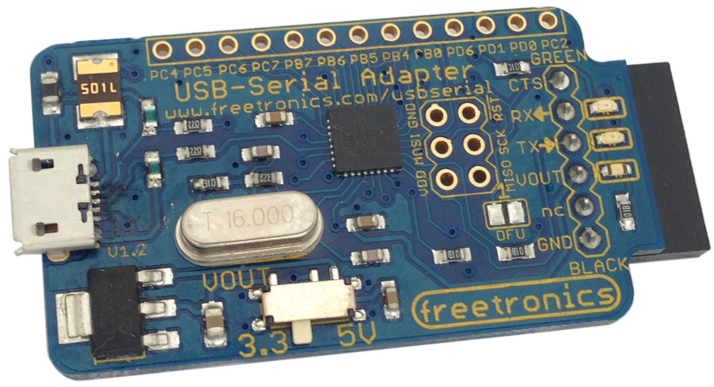
You’ll also need a USB-serial converter with support for 3.3V I/O. I used the Freetronics USB-Serial Converter (of course!), which has a switch that lets you select 3.3V or 5V mode.
For years I’ve been running my home automation switchboards using “temporary” controllers using Ethernet-enabled Arduino boards controlling DIN-rail mounted relays. My hope was that some day, someone would release a DIN-rail mounted control system with wired connectivity.
And now, all these years later, Allterco have done it. The new Shelly Pro 4PM looks like exactly the device I’ve been waiting for.
Disclosure: Allterco sent me this pre-release unit free of charge. However, I have personally paid for Shellys in the past and I’m sure I will in future. They had no input into this video, which is my own honest assessment of the Pro 4PM.
The Shelly Pro 4PM supports MQTT control out of the box. All you need to go is go into the MQTT configuration menu, put in the details for your broker, and it will be ready to go.
The MQTT topics are based on the device ID of the specific Shelly module, but converted to lower case. You can find the ID by opening the web interface and looking at the bottom:
The topic for sending commands to the Shelly is of the form:
shellypro4pm-<device_id>/rpc
So based on the device ID in the screenshot above, you can see the command topic would be:
shellypro4pm-84cca87e4a80/rpc
Messages are sent and received as JSON. To turn on an output, send a message to the command topic of the form:
This example turns on the first channel, because in the “params” section it has the ID set to 0 and the “on” value set to “true”. To turn off the first channel, change the “on” value to “false”.
Turn control the second channel, use the id “1”, and so on.
To see events published by the Shelly, including when channels change state and how much power each device is using, subscribe to the topic of the form:
ESP8266, ESP8285, and ESP32 microcontrollers are commonly designed into projects with a programming header, to allow initial flashing of firmware. Espressif produces a programmer / debugger board called “ESP-Prog”, but they’re almost unknown so there has been very little standardisation on the format of programming headers. Everyone who designs their own board invents their own header format.
This document outlines the conventions that I have decided to follow for my own ESPxx projects, based on a review of existing header formats, discussions with many other board designers, Espressif documentation, and my own whims.
“ESPFlash” is the name of the header format. The ESPFlash GitHub repo contains an EAGLE CAD library for all ESPFlash header footprint variations, with ESP-JTAG headers as well. There are also pinout images: github.com/SuperHouse/ESPFlash
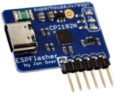
“ESPFlasher” is the reference implementation of a programming module using the ESPFlash header. Feel free to use the design or adapt it to suit your own requirements: github.com/SuperHouse/ESPFlasher
Compatible Programmers
ESPFlasher by Jonathan Oxer (SuperHouse Automation)
GPIO0 (hold LOW during startup to enter bootloader mode)
Header Options
The header can use either 2×3 or 1×6 format, in either 2.54mm (0.1″) or 1.27mm (0.05″) pitch.
Rationale for supporting 2×3 format: The Espressif reference design uses 2×3 format. This format is useful for a programmer connected via an IDC cable.
Rationale for supporting 1×6 format: Most hobby projects tend to use a linear format, and popular boards such as the Sonoff often do as well. This format works well on the edge of a PCB, and is best when the intention is to permanently solder the programming board onto the target board.
Rationale for supporting both 2.54mm and 1.27mm pitch: The Espressif reference design specifies use of either 2.54mm or 1.27mm pitch. Hobby projects tend to use 2.54mm pitch because it’s commonly available, large enough to handle easily, and jumper wires are readily available in this size. Providing 1.27mm pitch as an option is desirable for small boards with tight space.
This effectively gives 4 possible headers that can be used:
1×6 with 2.54mm pitch
1×6 with 1.27mm pitch
2×3 with 2.54mm pitch
2×3 with 1.27mm pitch
Ideally, there should be only one standard header. Having 4 possible header formats could lead to confusion, but at least the confusion will be minimised if there is consistency of pinout. Also, size adapters are trivial to make so it doesn’t require people to own 4 different programmers. A general-purpose programmer could easily support all 4 formats, or a programmer could be optimised for one specific format.
I expect that the most common format will be 1×6 @ 2.54mm.
1×6 Header Format
The 1×6 header format is an extension of the 4-pin header commonly used on Sonoff boards. The Sonoff programming header includes the first 4 pins of this format.
Connector on target: 1×6 socket, in either 2.54mm or 1.27mm pitch. Connector on programmer: 1×6 pin header, with pitch to match target.
ESPFlash 1×6 header pinout
Pin
Purpose
Notes
1
GND
Common ground between programmer and target board.
2
ESP_TXD
Tx pin on target board. Rx on programmer.
3
ESP_RXD
Rx pin on target board. Tx on programmer.
4
3.3V
3.3V supplied to target board by programmer. 600mA minimum.
5
ESP_EN
Enable (reset) pin on target board.
6
ESP_IO0
GPIO0 on target board.
2×3 Header Format
The 2×3 header format is used by the Espressif programmer / debugger reference design, which stipulates a shrouded header to ensure correct orientation. However, normal pin headers can also be used if preferred.
Connector on target: 2×3 box header or pin header, in either 2.54mm or 1.27mm pitch. Connector on programmer: 2×3 socket or 2×3 IDC cable, with pitch to match target.
ESPFlash 2×3 header pinout
Pin
Purpose
Notes
1
ESP_EN
Enable (reset) pin on target board.
2
3.3V
3.3V supplied to target board by programmer. 600mA minimum.
3
ESP_TXD
Tx pin on target board. Rx on programmer.
4
GND
Common ground between programmer and target board.
Installing Tasmota onto a device such as a Sonoff is usually done using esptool.py, which is a powerful command line utility but it can be a bit confusing if you’re not used to it. Now it’s been paired with an amazing graphical interface called Tasmotizer that gives you point-and-click convenience, and adds some handy features for configuring your devices:
The Tasmotizer page has good installation instructions, with three options given.
If you use Windows, download the executible and run it.
On Linux or MacOS, you can install using Pip.
If you want the absolute latest development version you can clone the Git repo and install manually.
Use whichever method suits you best. I used Pip to install it on my iMac, my Macbook Pro, and my Ubuntu desktop, and the process went smoothly on all of them. Make sure you have the latest version of Pip, and then use it to install Tasmotizer:
If your Python installation is set up so that new programs are automatically available, it should be possible to simply type in the name and press “Enter”:
tasmotizer.py
However, you may not be so lucky. You may have to find where Pip installed it. Pip can tell you where the files are for a specific package, but its output has horrible formatting that’s hard to interpret. Run this command to see a list of all the files in the Tasmotizer package:
pip3 show -f tasmotizer
The output will include a line called “Location” which shows the directory where the program is located. On my iMac, Pip installed Tasmotizer at:
It’s a pity that Python’s installation management is such a mess, and produces unpredictable results. Hopefully you can find the location for your installation without too many problems.
Once you’ve discovered its location, paste in the appropriate command and press “Enter” to launch Tasmotizer.
Connect the device to your computer
Your target device needs to be connected to your computer using USB, either by directly plugging in a cable or by using a USB-to-Serial adapter. Some devices such as Wemos D1 Mini boards have built-in USB. Sonoff boards don’t have USB so you’ll need to make up an adapter to suit the programming header for your specific board. I’ve done many videos and guides for reflashing various Sonoff models, and the Tasmota site has excellent documentation so follow the appropriate guide to make the connections.
Most Sonoff models use a simple 4-pin header, so I designed the Sonoff Programming Adapter to make it easy to plug in a 3.3V USB-to-Serial adapter with a standard 6-pin header.
Place device into bootloader mode
The ESP8266 / ESP8285 processor needs to be placed into a special bootloader mode before it can have Tasmota installed. This is done by powering it up while the GPIO0 pin is held at 0V, which is usually done using the control button. The sequence is:
Press and hold the button.
Connect power.
Wait a couple of seconds, then release the button.
The device then stays in bootloader mode, waiting for new software to be loaded.
Select device in Tasmotizer
Click the “Refresh” button so Tasmotizer will scan for connected devices and update its list. Use the drop-down to find your target device.
Select the firmware image
Tasmotizer gives you three options for selecting a firmware image.
If you have your own binary, such as a version of Tasmota or some other firmware that you’ve compiled or downloaded, click the “BIN file” radio button and select the file from your local disk.
If you want to install the current release version of Tasmota, click the “Release” radio button and then use the drop-down menu to select the specific flavour of Tasmota for your device.
If you like to live on the edge, you can click the “Development” radio button and use the latest development code that hasn’t been released yet.
Set flashing options
If you want Tasmotizer to make a backup of the existing software on your device, click the “Backup original firmware” option. This will allow you to put it back onto the device later if you change your mind.
If you want to make sure the entire memory of the device is cleared, click the “Erase before flashing” option. This makes sure there is nothing remaining from the previous firmware still left on the device, such as saved configuration options. This is a good idea to make sure you have a fresh start and Tasmota won’t read data from a previous installation.
Flash the firmware
With the correct firmware image selected, click the blue “Tasmotize!” button. Tasmotizer will download the selected image (if required) and install it onto your device.
You’ll see a progress bar as the image is installed. Once it’s done, you’ll be prompted to restart it.
Congratulations! Tasmota is installed.
If you want to configure it manually you can do that by following the usual Tasmota instructions. However, Tasmotizer can save you a lot of time by allowing you to do some basic configuration via USB while it’s still connected to your computer.
Select config options
Click the “Send config” button to open a configuration window.
WiFi setup
Click the check-box to enable the WiFi section, and enter your WiFi network name and password.
Module/template setup
Click the check-box to enable module/template setup, which gives you options to either select a pre-defined module or apply a template. Applying a module profile or a template allows your device to be configured entirely from Tasmotizer.
If you have a common device, select “Module” and find the device in the drop-down list.
If you have a device that has a template provided for it, select “Template” and then paste the template into the text box. There are more than 1000 templates provided at the Tasmota Device Templates Repository.
MQTT setup
If you use MQTT in your home automation system, click the check-box to enable MQTT setup and put in the address of your MQTT broker.
You can manually define the topic for this device (such as “bedroom1”) but my personal preference is to allow the device to generate the topic based on its own internal ID. That way all devices come up with their own unique topics, which can then be referenced in the home automation system.
To do that, change the “Topic” setting to add the extension “-%06X”, like this:
tasmota-%06X
What this will do is take the last 6 hexadecimal digits of the device ID and append them, so the topic will be something like “tasmota-6A0B15”. This value is then used to generate the FullTopic value below it automatically, by replacing the “%topic%” placeholder. The result will be full topics that look similar to:
I like this approach because it means that all my Tasmota devices can have the same configuration, but they still end up with unique MQTT topics.
Send config to device
With all your preferred options set, click the “Save” button. Tasmotizer will send your configuration to the device, and you’re all done. This step is a bit strange, because it happens so fast that it seems like it couldn’t possibly have done anything, but if you get a confirmation dialog then you’re all set.
Finished! Your Tasmota device will now reboot and apply the settings that you configured, so after a few seconds it will be on your network. Just follow the Tasmota documentation to learn how to link it to your home automation system.
ESP8266, ESP8285, and ESP32 microcontrollers are commonly designed into projects with a programming header, to allow initial flashing of firmware. Espressif produced a limited number of programmer / debugger boards, but they’re almost unknown so there has been very little standardisation on the format of programming headers. Everyone who starts their own project invents their own header format.
This document outlines the conventions that I have decided to follow for my own ESPXXxx projects, based on a review of existing header formats, discussions with many other board designers, Espressif documentation, and my own whims.
The more people who follow these conventions with their own designs, the better it will be for everyone.
Pins Required
GND
VDD (3.3V)
TX (3.3V)
RX (3.3V)
GPIO0 (hold LOW during startup to enter bootloader mode)
RESET (CH_EN, marked as “ESP_EN” below)
Header Options
The header can use either 2×3 or 1×6 format, in either 2.54mm (0.1″) or 1.27mm (0.05″) pitch.
Rationale for supporting 2×3 format: The Espressif reference design uses 2×3 format. This format is useful for minimising the footprint on the target board, so including this in the convention is useful. This format is also best for use with a programmer connected via an IDC cable.
Rationale for supporting 1×6 format: Most hobby projects tend to use a linear format, and popular boards such as the Sonoff often do as well.
Rationale for supporting both 2.54mm and 1.27mm pitch: The Espressif reference design specifies use of either 2.54mm or 1.27mm pitch. Hobby projects tend to use 2.54mm pitch because it’s commonly available, large enough to handle easily, and jumper wires are readily available in this size. Providing 1.27mm pitch as an option is desirable for small boards with tight space.
This effectively gives 4 possible headers that can be used:
1×6, 2.54mm pitch
1×6, 1.27mm pitch
2×3, 2.54mm pitch
2×3, 1.27mm pitch
Ideally, there should be only one standard header. Having 4 possible header formats could lead to confusion, but at least the confusion will be minimised if there is consistency of pinout. Also, size adapters are trivial to make so it doesn’t require people to own 4 different programmers. A general-purpose programmer could easily support all 4 formats, or a programmer could be optimised for one specific format.
I expect that the most common format will be 1×6 @ 2.54mm, followed by 2×3 @ 2.54mm.
1×6 Header Format
The 1×6 header format matches the pinout of the ESProg programming header.
Connector on target: 1×6 socket, in either 2.54mm or 1.27mm pitch. Connector on programmer: 1×6 pin header, in pitch to match target.
Pin
Purpose
Notes
1
ESP_IO0
2
ES_EN
3
GND
4
ESP_TXD
Tx pin on target board. Rx on programmer.
5
ESP_RXD
Rx pin on target board. Tx on programmer.
6
VDD
3.3V supplied to target board by programmer. 600mA minimum.
2×3 Header Format
The 2×3 header format is used by the Espressif programmer / debugger reference design, which stipulates a box-header to ensure correct orientation. However, normal pin headers can also be used if preferred.
Connector on target: 2×3 box header or pin header, in either 2.54mm or 1.27mm pitch. Connector on programmer: 2×3 socket or 2×3 IDC cable, in pitch to match target.
Pin
Purpose
Notes
1
ESP_EN
2
VDD
3.3V supplied to target board by programmer. 600mA minimum.
3
ESP_TXD
Tx pin on target board. Rx on programmer.
4
GND
5
ESP_RXD
Rx pin on target board. Tx on programmer.
6
ESP_IO0
Note: This draft is outdated and is left here for reference only. Do not use it in new designs!
ESP8266, ESP8285, and ESP32 microcontrollers are commonly designed into projects with a programming header, to allow initial flashing of firmware. Espressif produces a programmer / debugger board, but they’re almost unknown so there has been very little standardisation on the format of programming headers. Everyone who designs their own board invents their own header format.
This document outlines the conventions that I have decided to follow for my own ESPxx projects, based on a review of existing header formats, discussions with many other board designers, Espressif documentation, and my own whims.
The more people who follow these conventions for their own designs, the better it will be for everyone.
Pins Required
GND
VDD (3.3V)
TX (3.3V)
RX (3.3V)
GPIO0 (hold LOW during startup to enter bootloader mode)
RESET (CH_EN, marked as “ESP_EN” below)
Header Options
The header can use either 2×3 or 1×6 format, in either 2.54mm (0.1″) or 1.27mm (0.05″) pitch.
Rationale for supporting 2×3 format: The Espressif reference design uses 2×3 format. This format is useful for a programmer connected via an IDC cable.
Rationale for supporting 1×6 format: Most hobby projects tend to use a linear format, and popular boards such as the Sonoff often do as well. This format works well on the edge of a PCB, and is best when the intention is to permanently solder the programming board onto the target board.
Rationale for supporting both 2.54mm and 1.27mm pitch: The Espressif reference design specifies use of either 2.54mm or 1.27mm pitch. Hobby projects tend to use 2.54mm pitch because it’s commonly available, large enough to handle easily, and jumper wires are readily available in this size. Providing 1.27mm pitch as an option is desirable for small boards with tight space.
This effectively gives 4 possible headers that can be used:
1×6, 2.54mm pitch
1×6, 1.27mm pitch
2×3, 2.54mm pitch
2×3, 1.27mm pitch
Ideally, there should be only one standard header. Having 4 possible header formats could lead to confusion, but at least the confusion will be minimised if there is consistency of pinout. Also, size adapters are trivial to make so it doesn’t require people to own 4 different programmers. A general-purpose programmer could easily support all 4 formats, or a programmer could be optimised for one specific format.
I expect that the most common format will be 1×6 @ 2.54mm.
1×6 Header Format
The 1×6 header format is an extension of the 4-pin header commonly used on Sonoff boards. The Sonoff programming header includes the first 4 pins of this format.
Connector on target: 1×6 socket, in either 2.54mm or 1.27mm pitch. Connector on programmer: 1×6 pin header, in pitch to match target.
Pin
Purpose
Notes
1
GND
Common ground between programmer and target board.
2
ESP_TXD
Tx pin on target board. Rx on programmer.
3
ESP_RXD
Rx pin on target board. Tx on programmer.
4
3.3V
3.3V supplied to target board by programmer. 600mA minimum.
5
ESP_EN
Enable (reset) pin on target board.
6
ESP_IO0
GPIO0 on target board.
2×3 Header Format
The 2×3 header format is used by the Espressif programmer / debugger reference design, which stipulates a shrouded header to ensure correct orientation. However, normal pin headers can also be used if preferred.
Connector on target: 2×3 box header or pin header, in either 2.54mm or 1.27mm pitch. Connector on programmer: 2×3 socket or 2×3 IDC cable, in pitch to match target.
Pin
Purpose
Notes
1
ESP_EN
Enable (reset) pin on target board.
2
3.3V
3.3V supplied to target board by programmer. 600mA minimum.
3
ESP_TXD
Tx pin on target board. Rx on programmer.
4
GND
Common ground between programmer and target board.
5
ESP_RXD
Rx pin on target board. Tx on programmer.
6
ESP_IO0
GPIO0 on target board.
Note: This draft is outdated and is left here for reference only. Do not use it in new designs!
If you don’t put USB on your project, you have to decide on a programming header to use. But everyone does it their own way: Sonoff has theirs, wESP32 has another, many projects have them and they’re all different!
That sucks, so let’s fix it by deciding what we think should be the conventional programming header format for our projects.
My goals are:
Define a convention for programming headers on ESP8285, ESP8266, and ESP32 boards.
Use that header in our own projects, so that it becomes common and interchangeable.
Lobby ITEAD to use the same header in future Sonoff models.
And the stretch goal: Convince Espressif to document it as a recommended header format for new ESPxx projects.
If we’re super-lucky, maybe we can convince ITEAD to fix the incomplete Sonoff programming header by adding RESET and GPIO0, and make all our lives easier in future.
We need to decide on a physical format, and also whether to supply 3.3V or 5V to the target board from the programmer. The pins we need are:
GND
VCC
TX
RX
GPIO0
RESET
Physical format options include:
1×6 0.1″ header
2×3 0.1″ header
1×6 2mm header
2×3 2mm header
Something else? Ideas please!
Design considerations
The design considerations for the physical format include:
Similarity to existing designs including Sonoff, wESP32, ESProg, and ESP32 Programmer
Cheap and easy to use, with easy to source connectors
Small footprint on the target device
Perhaps leverage some existing standard such as P-MOD
Ability to mount permanently as a sub-board in the project if required
Considerations for the choice of 3.3V or 5V include:
Sonoff already requires 3.3V on the header
5V can be useful in some cases
Switchable voltage would be possible, but could be dangerous and would lead to fragmentation of the convention
Connection of programmer directly to VCC on target, compared to input of onboard 3.3V VREG
Interesting options
ESP-01 header
This has the advantage that it’s well documented, and many people have made adapters for it.
wESP32-Prog header
Already implemented on the wEPS32. 5V supply means the input can be diode-isolated from other supply sources on the board. 4 of the pins match the Sonoff header, except that Sonoff requires 3.3V so it’s not a perfect match.
wESP32-Prog header, but with 3.3V
This is the closest we could have to matching the Sonoff header while extending it to add the GPIO0 and RESET lines.
ESP-Prog header
Documented by Espressif. Uses a 2×3 header, which is nice in terms of compact size. Unfortunately there’s no useful overlap with the ESP-01 header.
ESProg header
Doesn’t seem to match up with anything else in terms of pin order, but is perhaps the closest match electrically in a 1×6 format: all the necessary pins, with 3.3V supplied.
ESP32 Programmer by Mike Rankin
Nice 2×3 format header. If power was added this would be a nice format, but it doesn’t have anything to differentiate it from the ESP-Prog format from Espressif.
Other ESP32 Programmer by Mike Rankin
This one has a 1×5 header, which has all the pins we want except power.
My friend Karl von Moller came along with me and a few others on a recent trip to Shenzhen, China. Karl is a film-maker so he documented the trip extensively, and the first episode about the trip is up now:
He’ll be following up with more videos about what we saw on the trip, and my own video about our tour of ITEAD and visit to the Sonoff factory will be up soon too.
Plugs into a USB port on your computer and provides you with a hardware serial interface: perfect for giving your home-brew Arduino-compatible projects a USB interface compatible with the Arduino IDE.
Particularly useful when reflashing Sonoff devices, because the output can be switched to 3.3V.
Provides a 6-way female connector with pinout matching the popular FTDI cable. Just plug it into a header intended for an FTDI connection, and you’re good to go.
But this board is so much more than just a USB to serial adapter: it’s actually a really useful general purpose breakout for the ATmega16u2 MCU! We’ve included headers along the edge of the PCB for the rest of the I/O pins, so you can re-flash the board with whatever firmware you like and use it as a general purpose 16u2 development board.