ESP8266, ESP8285, and ESP32 microcontrollers are commonly designed into projects with a programming header, to allow initial flashing of firmware. Espressif produces a programmer / debugger board called “ESP-Prog”, but they’re almost unknown so there has been very little standardisation on the format of programming headers. Everyone who designs their own board invents their own header format.
This document outlines the conventions that I have decided to follow for my own ESPxx projects, based on a review of existing header formats, discussions with many other board designers, Espressif documentation, and my own whims.
For more background information see these videos:
* Vlog #66: Let’s define a standard ESP8266/ESP32 programming header
* SuperHouse #42: The ESPFlash programming header for ESP8266 / ESP32
Resources
“ESPFlash” is the name of the header format. The ESPFlash GitHub repo contains an EAGLE CAD library for all ESPFlash header footprint variations, with ESP-JTAG headers as well. There are also pinout images: github.com/SuperHouse/ESPFlash
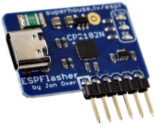
“ESPFlasher” is the reference implementation of a programming module using the ESPFlash header. Feel free to use the design or adapt it to suit your own requirements: github.com/SuperHouse/ESPFlasher
Compatible Programmers
- ESPFlasher by Jonathan Oxer (SuperHouse Automation)
- Eflashy32 by Greg Cormier
- ESP232 by Joshua Dennis (Dennistries Ltd)
Pins Required
- GND
- VDD (3.3V)
- TX (3.3V)
- RX (3.3V)
- RESET (CH_EN, marked as “ESP_EN” below)
- GPIO0 (hold LOW during startup to enter bootloader mode)
Header Options
The header can use either 2×3 or 1×6 format, in either 2.54mm (0.1″) or 1.27mm (0.05″) pitch.
Rationale for supporting 2×3 format: The Espressif reference design uses 2×3 format. This format is useful for a programmer connected via an IDC cable.
Rationale for supporting 1×6 format: Most hobby projects tend to use a linear format, and popular boards such as the Sonoff often do as well. This format works well on the edge of a PCB, and is best when the intention is to permanently solder the programming board onto the target board.
Rationale for supporting both 2.54mm and 1.27mm pitch: The Espressif reference design specifies use of either 2.54mm or 1.27mm pitch. Hobby projects tend to use 2.54mm pitch because it’s commonly available, large enough to handle easily, and jumper wires are readily available in this size. Providing 1.27mm pitch as an option is desirable for small boards with tight space.
This effectively gives 4 possible headers that can be used:
- 1×6 with 2.54mm pitch
- 1×6 with 1.27mm pitch
- 2×3 with 2.54mm pitch
- 2×3 with 1.27mm pitch
Ideally, there should be only one standard header. Having 4 possible header formats could lead to confusion, but at least the confusion will be minimised if there is consistency of pinout. Also, size adapters are trivial to make so it doesn’t require people to own 4 different programmers. A general-purpose programmer could easily support all 4 formats, or a programmer could be optimised for one specific format.
I expect that the most common format will be 1×6 @ 2.54mm.

1×6 Header Format
The 1×6 header format is an extension of the 4-pin header commonly used on Sonoff boards. The Sonoff programming header includes the first 4 pins of this format.
Connector on target: 1×6 socket, in either 2.54mm or 1.27mm pitch.
Connector on programmer: 1×6 pin header, with pitch to match target.

| Pin | Purpose | Notes |
| 1 | GND | Common ground between programmer and target board. |
| 2 | ESP_TXD | Tx pin on target board. Rx on programmer. |
| 3 | ESP_RXD | Rx pin on target board. Tx on programmer. |
| 4 | 3.3V | 3.3V supplied to target board by programmer. 600mA minimum. |
| 5 | ESP_EN | Enable (reset) pin on target board. |
| 6 | ESP_IO0 | GPIO0 on target board. |
2×3 Header Format
The 2×3 header format is used by the Espressif programmer / debugger reference design, which stipulates a shrouded header to ensure correct orientation. However, normal pin headers can also be used if preferred.
Connector on target: 2×3 box header or pin header, in either 2.54mm or 1.27mm pitch.
Connector on programmer: 2×3 socket or 2×3 IDC cable, with pitch to match target.

| Pin | Purpose | Notes |
| 1 | ESP_EN | Enable (reset) pin on target board. |
| 2 | 3.3V | 3.3V supplied to target board by programmer. 600mA minimum. |
| 3 | ESP_TXD | Tx pin on target board. Rx on programmer. |
| 4 | GND | Common ground between programmer and target board. |
| 5 | ESP_RXD | Rx pin on target board. Tx on programmer. |
| 6 | ESP_IO0 | GPIO0 on target board. |
